在開始Configuration Bits教學前,要先確認你的硬體接線是否有正確,請參考我之前的這篇PIC18F25K83硬體介紹的文章,對於PIC18F25K83的微處理機來說,Configuration Bits會設定一些基礎的核心設定(例如時脈等),大部分的時候你的設定都會是類似的,但有時也會因為有特殊需求,會需要修改這裡的設定。
另外會因為每個人使用的PIC晶片不同,Configuration Bits顯示的文字就會改變,可以參考那顆晶片的Datasheet,我使用PIC18F25K83作為範例,但大致的設定邏輯都是一樣的,時脈、看門狗這些,都要記得設定。
PIC18F25K83的Datasheet順便給你參考:
首先開啟你的Configuration Bits
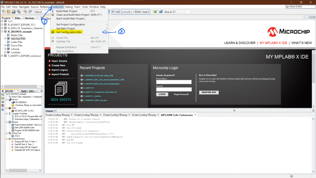
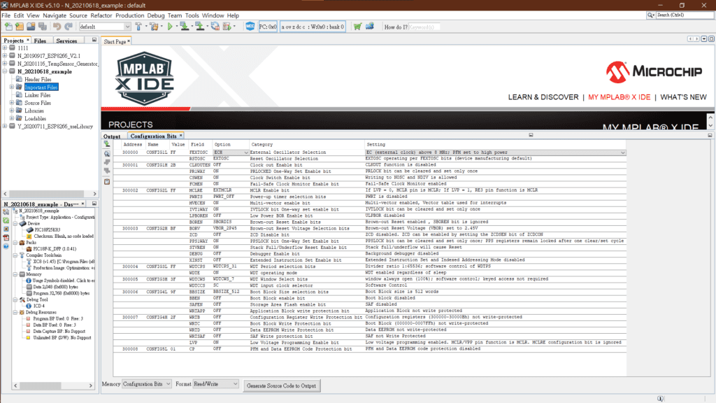
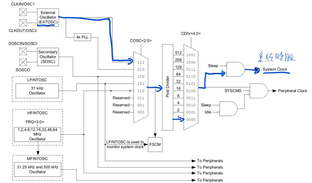
參考PIC18F25K83的Datasheet中的第7章和第11章,得知Configuration Bits有兩個要改分別是:
- FEXTOSC(External Oscillator Selection;外接石英震盪器):選擇HS,因為我接16MHz的石英震盪器做為微處理機的系統時脈。

- WDTE(WDT operating mode;看門狗…不是遊戲的那個…) :選擇OFF,若選擇ON的話,若在設定的時間內不將其計時器歸零的話,會當成微處理機當機,自動重置系統,會變成一直在重新重置系統,沒有動作反應。這篇文章有更詳細的說明。
CP的設定千萬不要動到,一定要設為OFF!!!
CP的設定千萬不要動到,一定要設為OFF!!!
CP的設定千萬不要動到,一定要設為OFF!!!
若將它設為ON,會導致程式無法重複進行燒錄,會將整顆晶片燒死,除非你是要做最終的產品,否則這個在開發階段都要設為OFF。
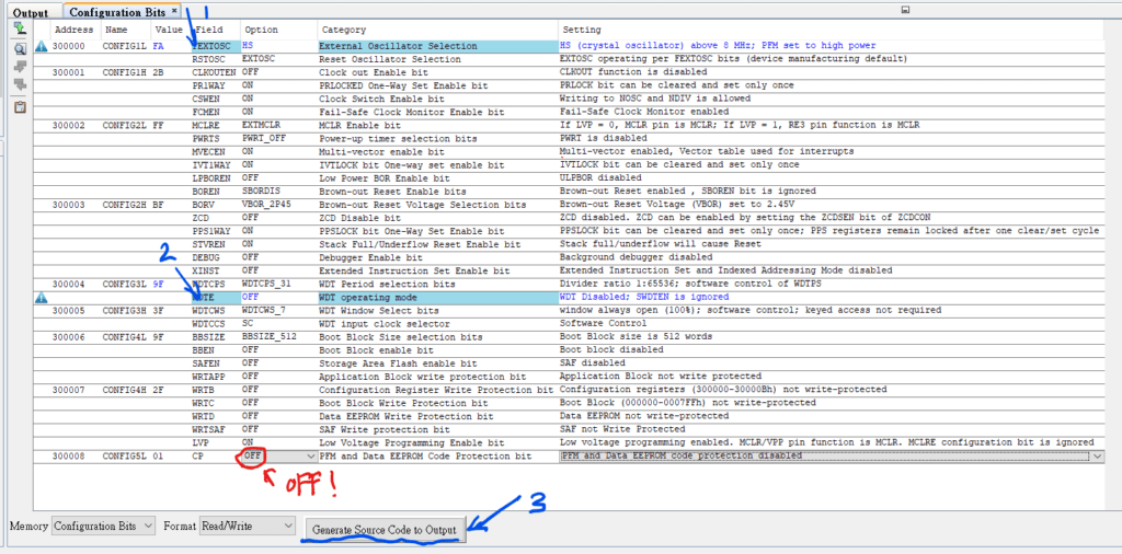
按下Generate Source Code to Output,產生基礎的設定碼。
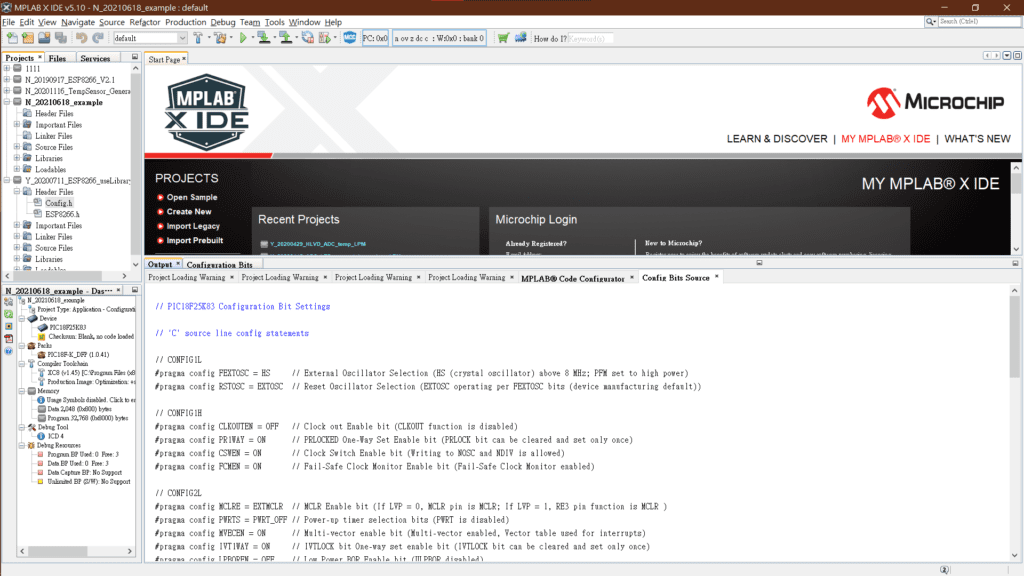
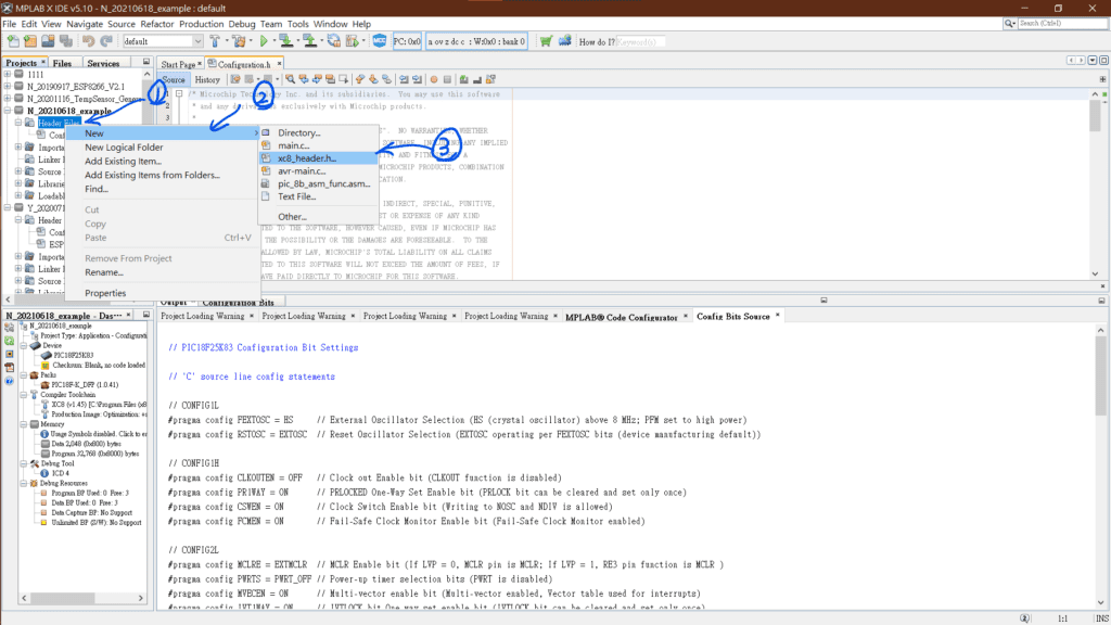
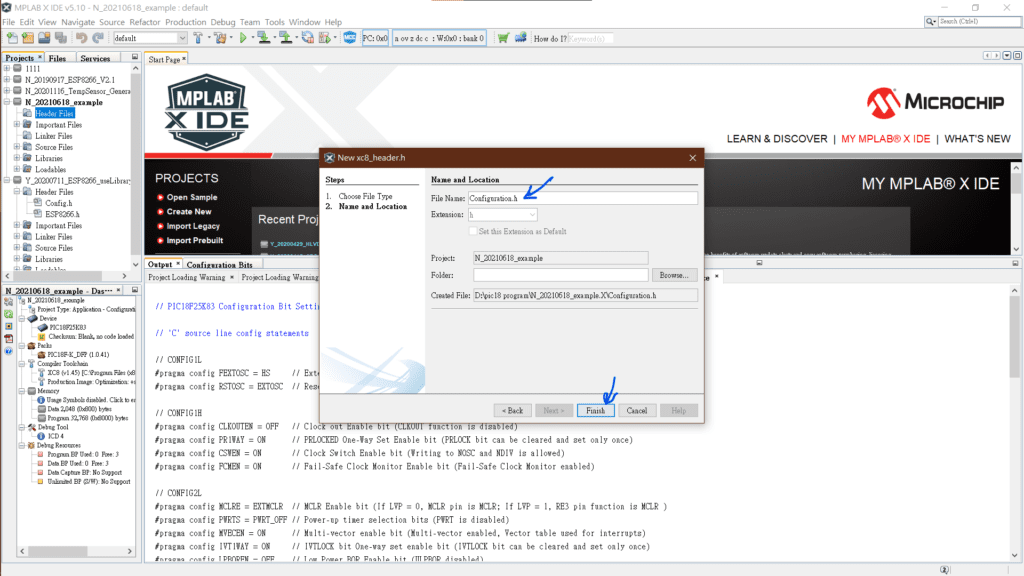
在剛剛新增的專案中,創建一個標頭(Configuration.h)檔案,用來放剛剛Configuration Bits產生出來的程式碼。
全選並複製產生出來的程式碼
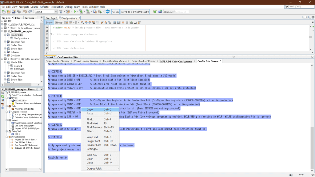
刪除掉「include <xc.h>」到「ifdef __cplusplus」中間的灰色註解(藍色X的部分),並貼上剛剛複製的程式碼,記得存檔!
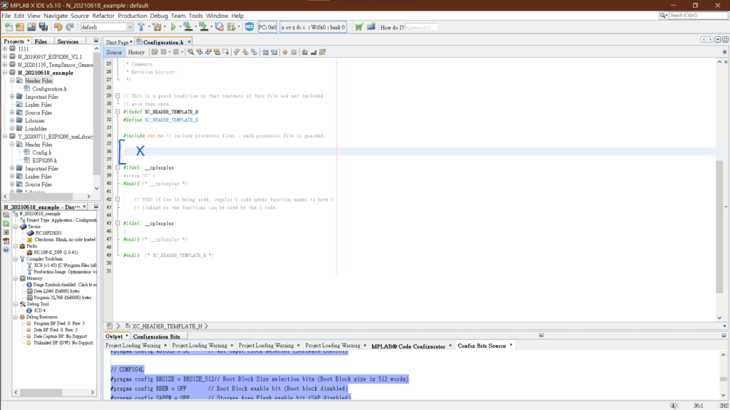
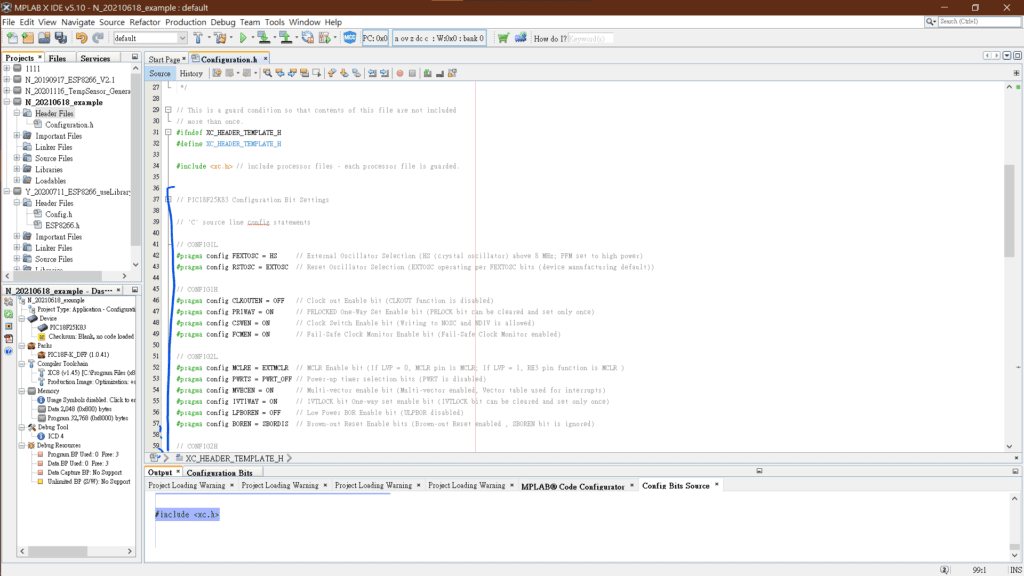
完整的Configuration.h的程式碼長得如下:
/* Microchip Technology Inc. and its subsidiaries.  You may use this software
 * and any derivatives exclusively with Microchip products.
 *
 * THIS SOFTWARE IS SUPPLIED BY MICROCHIP "AS IS".  NO WARRANTIES, WHETHER
 * EXPRESS, IMPLIED OR STATUTORY, APPLY TO THIS SOFTWARE, INCLUDING ANY IMPLIED
 * WARRANTIES OF NON-INFRINGEMENT, MERCHANTABILITY, AND FITNESS FOR A
 * PARTICULAR PURPOSE, OR ITS INTERACTION WITH MICROCHIP PRODUCTS, COMBINATION
 * WITH ANY OTHER PRODUCTS, OR USE IN ANY APPLICATION.
 *
 * IN NO EVENT WILL MICROCHIP BE LIABLE FOR ANY INDIRECT, SPECIAL, PUNITIVE,
 * INCIDENTAL OR CONSEQUENTIAL LOSS, DAMAGE, COST OR EXPENSE OF ANY KIND
 * WHATSOEVER RELATED TO THE SOFTWARE, HOWEVER CAUSED, EVEN IF MICROCHIP HAS
 * BEEN ADVISED OF THE POSSIBILITY OR THE DAMAGES ARE FORESEEABLE.  TO THE
 * FULLEST EXTENT ALLOWED BY LAW, MICROCHIP'S TOTAL LIABILITY ON ALL CLAIMS
 * IN ANY WAY RELATED TO THIS SOFTWARE WILL NOT EXCEED THE AMOUNT OF FEES, IF
 * ANY, THAT YOU HAVE PAID DIRECTLY TO MICROCHIP FOR THIS SOFTWARE.
 *
 * MICROCHIP PROVIDES THIS SOFTWARE CONDITIONALLY UPON YOUR ACCEPTANCE OF THESE
 * TERMS.
 */

/*
 * File:
 * Author:
 * Comments:
 * Revision history:
 */

// This is a guard condition so that contents of this file are not included
// more than once.
#ifndef XC_HEADER_TEMPLATE_H
#define	XC_HEADER_TEMPLATE_H

#include  // include processor files - each processor file is guarded.


// PIC18F25K83 Configuration Bit Settings

// 'C' source line config statements

// CONFIG1L
#pragma config FEXTOSC = HS     // External Oscillator Selection (HS (crystal oscillator) above 8 MHz; PFM set to high power)
#pragma config RSTOSC = EXTOSC  // Reset Oscillator Selection (EXTOSC operating per FEXTOSC bits (device manufacturing default))

// CONFIG1H
#pragma config CLKOUTEN = OFF   // Clock out Enable bit (CLKOUT function is disabled)
#pragma config PR1WAY = ON      // PRLOCKED One-Way Set Enable bit (PRLOCK bit can be cleared and set only once)
#pragma config CSWEN = ON       // Clock Switch Enable bit (Writing to NOSC and NDIV is allowed)
#pragma config FCMEN = ON       // Fail-Safe Clock Monitor Enable bit (Fail-Safe Clock Monitor enabled)

// CONFIG2L
#pragma config MCLRE = EXTMCLR  // MCLR Enable bit (If LVP = 0, MCLR pin is MCLR; If LVP = 1, RE3 pin function is MCLR )
#pragma config PWRTS = PWRT_OFF // Power-up timer selection bits (PWRT is disabled)
#pragma config MVECEN = ON      // Multi-vector enable bit (Multi-vector enabled, Vector table used for interrupts)
#pragma config IVT1WAY = ON     // IVTLOCK bit One-way set enable bit (IVTLOCK bit can be cleared and set only once)
#pragma config LPBOREN = OFF    // Low Power BOR Enable bit (ULPBOR disabled)
#pragma config BOREN = SBORDIS  // Brown-out Reset Enable bits (Brown-out Reset enabled , SBOREN bit is ignored)

// CONFIG2H
#pragma config BORV = VBOR_2P45 // Brown-out Reset Voltage Selection bits (Brown-out Reset Voltage (VBOR) set to 2.45V)
#pragma config ZCD = OFF        // ZCD Disable bit (ZCD disabled. ZCD can be enabled by setting the ZCDSEN bit of ZCDCON)
#pragma config PPS1WAY = ON     // PPSLOCK bit One-Way Set Enable bit (PPSLOCK bit can be cleared and set only once; PPS registers remain locked after one clear/set cycle)
#pragma config STVREN = ON      // Stack Full/Underflow Reset Enable bit (Stack full/underflow will cause Reset)
#pragma config DEBUG = OFF      // Debugger Enable bit (Background debugger disabled)
#pragma config XINST = OFF      // Extended Instruction Set Enable bit (Extended Instruction Set and Indexed Addressing Mode disabled)

// CONFIG3L
#pragma config WDTCPS = WDTCPS_31// WDT Period selection bits (Divider ratio 1:65536; software control of WDTPS)
#pragma config WDTE = OFF       // WDT operating mode (WDT Disabled; SWDTEN is ignored)

// CONFIG3H
#pragma config WDTCWS = WDTCWS_7// WDT Window Select bits (window always open (100%); software control; keyed access not required)
#pragma config WDTCCS = SC      // WDT input clock selector (Software Control)

// CONFIG4L
#pragma config BBSIZE = BBSIZE_512// Boot Block Size selection bits (Boot Block size is 512 words)
#pragma config BBEN = OFF       // Boot Block enable bit (Boot block disabled)
#pragma config SAFEN = OFF      // Storage Area Flash enable bit (SAF disabled)
#pragma config WRTAPP = OFF     // Application Block write protection bit (Application Block not write protected)

// CONFIG4H
#pragma config WRTB = OFF       // Configuration Register Write Protection bit (Configuration registers (300000-30000Bh) not write-protected)
#pragma config WRTC = OFF       // Boot Block Write Protection bit (Boot Block (000000-0007FFh) not write-protected)
#pragma config WRTD = OFF       // Data EEPROM Write Protection bit (Data EEPROM not write-protected)
#pragma config WRTSAF = OFF     // SAF Write protection bit (SAF not Write Protected)
#pragma config LVP = ON         // Low Voltage Programming Enable bit (Low voltage programming enabled. MCLR/VPP pin function is MCLR. MCLRE configuration bit is ignored)

// CONFIG5L
#pragma config CP = OFF         // PFM and Data EEPROM Code Protection bit (PFM and Data EEPROM code protection disabled)

// CONFIG5H

// #pragma config statements should precede project file includes.
// Use project enums instead of #define for ON and OFF.

#include


#ifdef	__cplusplus
extern "C" {
#endif /* __cplusplus */

    // TODO If C++ is being used, regular C code needs function names to have C
    // linkage so the functions can be used by the c code.

#ifdef	__cplusplus
}
#endif /* __cplusplus */

#endif	/* XC_HEADER_TEMPLATE_H */
當設定好核心的程式檔(Configuration.h),就來新增主程式(main.c)的檔案啦~
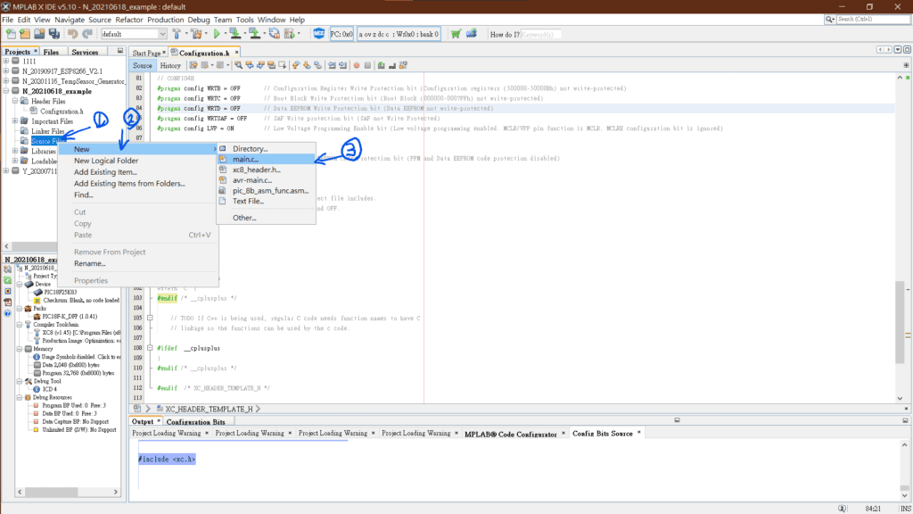
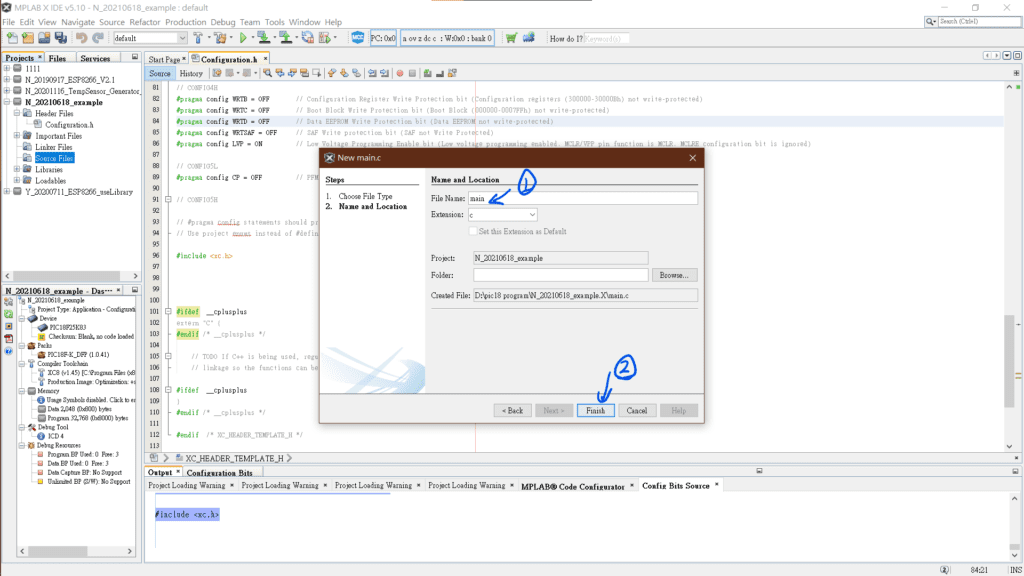
新增main.c檔案後,長的會像是這樣:
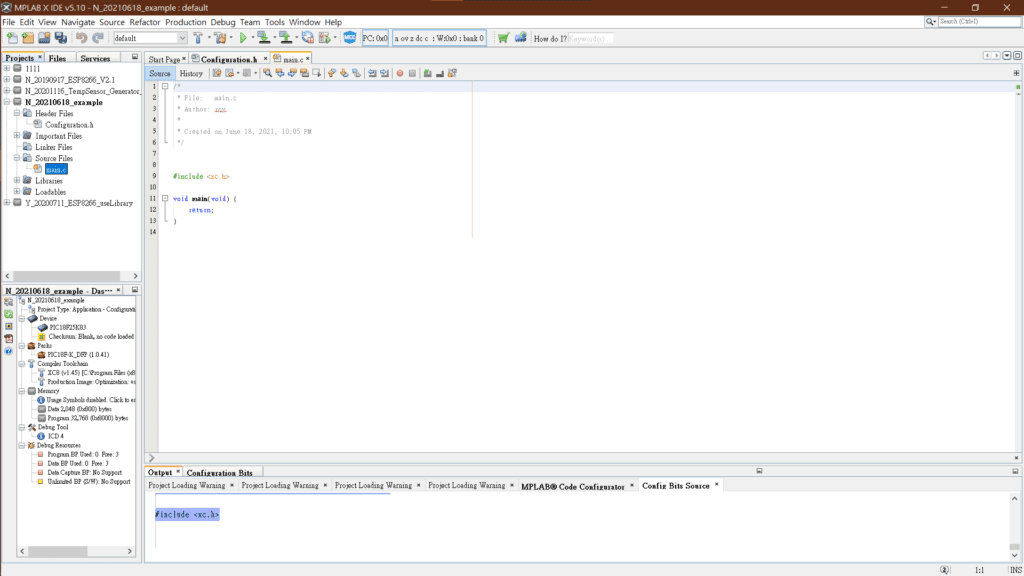
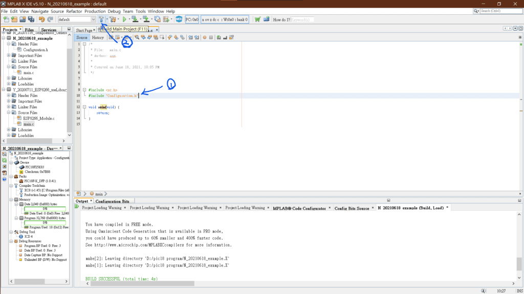
並在前面新增下面這一行程式碼,匯入剛剛我們設定的Configuration Bits的程式碼。
#include "Configuration.h"按下那根榔頭(Build Main Project F11),編譯程式,若程式下面顯示BUILD SUCCESSFUL,及代表程式編譯完成,接下來就可以開始寫你想要的功能啦!
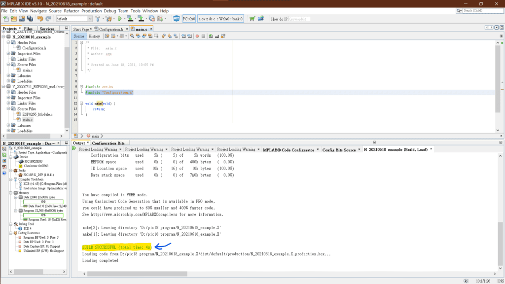
下面是main.c檔案的完整程式碼:
/*
 * File:   main.c
 * Author: roy
 *
 * Created on June 18, 2021, 10:05 PM
 */


#include
#include "Configuration.h"

void main(void) {
    return;
}
基本上的操作步驟是不管你寫甚麼功能時,都會需要做的建立與檢察,若有任何問題,歡迎在下面與我討論!

2 comments
[…] 基於上一篇文章「PIC18 Configuration Bits教學(基礎設定)」可以將PIC18的基礎設定設定完成,接下來這篇教學將教你如何用PIC18做一顆LED燈間隔一秒閃爍。 […]
[…] 恭喜你第一份專案開啟成功,如果有遇到困難的,歡迎在下面留言區與我討論❤❤,下一篇將開始講要如何設定PIC18以及燒錄PIC18程式啦! […]