目錄
基於上一篇文章「PIC18 Configuration Bits教學(基礎設定)」可以將PIC18的基礎設定設定完成,接下來這篇教學將教你如何用PIC18做一顆LED燈間隔一秒閃爍。
目錄
電路圖接線
完整的程式
Config Bits基礎設定
初始化設定
主程式
延伸思考
電路圖接線
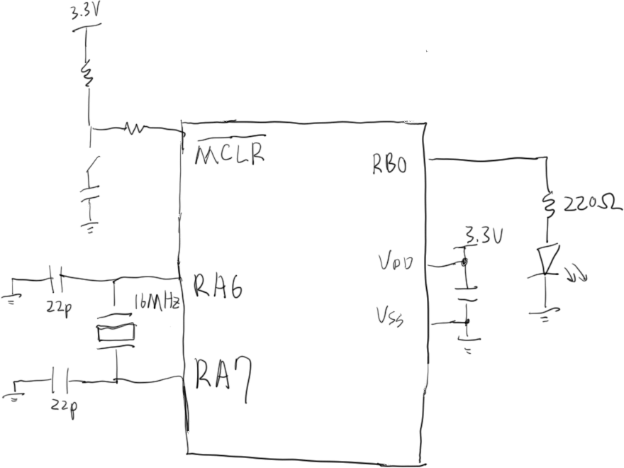
RB0為我們的LED燈輸出的腳位,MCLR要接reset按鈕,RA6、7接石英震盪器。(請接受我這畢卡索一般的畫.·´¯`(>▂<)´¯`·. )

完整的程式
/*
 * version:Y 2010707 V1.0
 * Blink the LED every second(RB0 output)
 * Config Bits:Watch dog timer:OFF、Extenal Oscillator(EXTTOSC)16MHZ(OSC1、OSC2)
*/
#include
#include "config.h"
#define _XTAL_FREQ 16000000
void Initial();

void main(void) {
    Initial();
    while(1){
        LATBbits.LATB0 = ~LATBbits.LATB0;
        __delay_ms(1000);
    }
    return;
}
void Initial(){
    TRISBbits.TRISB0 = 0;
    ANSELBbits.ANSELB0 = 1;
}
請點及此連結下載完整程式:
Config Bits基礎設定
Config Bits的基礎設定,做以下幾件事情:
// PIC18F25K83 Configuration Bit Settings

// 'C' source line config statements

// CONFIG1L
#pragma config FEXTOSC = HS     // External Oscillator Selection (HS (crystal oscillator) above 8 MHz; PFM set to high power)
#pragma config RSTOSC = EXTOSC  // Reset Oscillator Selection (EXTOSC operating per FEXTOSC bits (device manufacturing default))

// CONFIG1H
#pragma config CLKOUTEN = OFF   // Clock out Enable bit (CLKOUT function is disabled)
#pragma config PR1WAY = ON      // PRLOCKED One-Way Set Enable bit (PRLOCK bit can be cleared and set only once)
#pragma config CSWEN = ON       // Clock Switch Enable bit (Writing to NOSC and NDIV is allowed)
#pragma config FCMEN = ON       // Fail-Safe Clock Monitor Enable bit (Fail-Safe Clock Monitor enabled)

// CONFIG2L
#pragma config MCLRE = EXTMCLR  // MCLR Enable bit (If LVP = 0, MCLR pin is MCLR; If LVP = 1, RE3 pin function is MCLR )
#pragma config PWRTS = PWRT_OFF // Power-up timer selection bits (PWRT is disabled)
#pragma config MVECEN = ON      // Multi-vector enable bit (Multi-vector enabled, Vector table used for interrupts)
#pragma config IVT1WAY = ON     // IVTLOCK bit One-way set enable bit (IVTLOCK bit can be cleared and set only once)
#pragma config LPBOREN = OFF    // Low Power BOR Enable bit (ULPBOR disabled)
#pragma config BOREN = SBORDIS  // Brown-out Reset Enable bits (Brown-out Reset enabled , SBOREN bit is ignored)

// CONFIG2H
#pragma config BORV = VBOR_2P45 // Brown-out Reset Voltage Selection bits (Brown-out Reset Voltage (VBOR) set to 2.45V)
#pragma config ZCD = OFF        // ZCD Disable bit (ZCD disabled. ZCD can be enabled by setting the ZCDSEN bit of ZCDCON)
#pragma config PPS1WAY = ON     // PPSLOCK bit One-Way Set Enable bit (PPSLOCK bit can be cleared and set only once; PPS registers remain locked after one clear/set cycle)
#pragma config STVREN = ON      // Stack Full/Underflow Reset Enable bit (Stack full/underflow will cause Reset)
#pragma config DEBUG = OFF      // Debugger Enable bit (Background debugger disabled)
#pragma config XINST = OFF      // Extended Instruction Set Enable bit (Extended Instruction Set and Indexed Addressing Mode disabled)

// CONFIG3L
#pragma config WDTCPS = WDTCPS_31// WDT Period selection bits (Divider ratio 1:65536; software control of WDTPS)
#pragma config WDTE = OFF       // WDT operating mode (WDT Disabled; SWDTEN is ignored)

// CONFIG3H
#pragma config WDTCWS = WDTCWS_7// WDT Window Select bits (window always open (100%); software control; keyed access not required)
#pragma config WDTCCS = SC      // WDT input clock selector (Software Control)

// CONFIG4L
#pragma config BBSIZE = BBSIZE_512// Boot Block Size selection bits (Boot Block size is 512 words)
#pragma config BBEN = OFF       // Boot Block enable bit (Boot block disabled)
#pragma config SAFEN = OFF      // Storage Area Flash enable bit (SAF disabled)
#pragma config WRTAPP = OFF     // Application Block write protection bit (Application Block not write protected)

// CONFIG4H
#pragma config WRTB = OFF       // Configuration Register Write Protection bit (Configuration registers (300000-30000Bh) not write-protected)
#pragma config WRTC = OFF       // Boot Block Write Protection bit (Boot Block (000000-0007FFh) not write-protected)
#pragma config WRTD = OFF       // Data EEPROM Write Protection bit (Data EEPROM not write-protected)
#pragma config WRTSAF = OFF     // SAF Write protection bit (SAF not Write Protected)
#pragma config LVP = ON         // Low Voltage Programming Enable bit (Low voltage programming enabled. MCLR/VPP pin function is MCLR. MCLRE configuration bit is ignored)
// CONFIG5L
#pragma config CP = OFF         // PFM and Data EEPROM Code Protection bit (PFM and Data EEPROM code protection disabled)

// CONFIG5H

// #pragma config statements should precede project file includes.
// Use project enums instead of #define for ON and OFF.

#include
初始化設定
我習慣會將初始化設定都用一個副程式(void Initial)包住,即便他可能很簡短,但也會將用副程式寫起來,因為可以讓主程式比較容易理解哪一些事初始化設定。
void Initial(){
    TRISBbits.TRISB0 = 0;
    ANSELBbits.ANSELB0 = 1;
}
「TRISBbits.TRISB0 = 0;」。TRISX,在datasheet中用「Ctrl+F」搜尋TRIS可以找到這一頁,裡面有提到當該Bit設為1的時候會該腳位被設定為輸出,設為0時候該腳位會被設定為輸入。

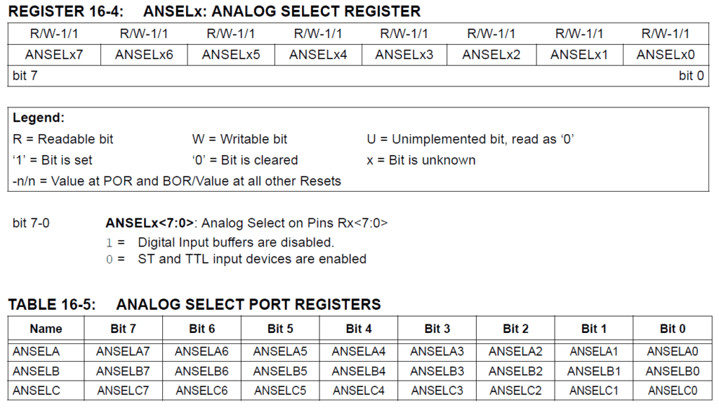
「ANSELBbits.ANSELB0 = 1;」從Datasheet去尋找ansel的關鍵字(第16章),可找這兩段資料,此暫存器可以設定此腳位是作為類比還是數位,若今天是要做ADC類比轉數位時,腳位要設為類比的,在這份專案中,我們先將其設為1,將此腳位設定為類比腳位。


主程式
主程式通常會包括在main裡面,為了要讓程式能重複無限次執行,使用while(1),也有人是使用for(;;),皆為重複無限次執行,在執行while(1)之前,會先呼叫Initial的副程式,執行初始化設定,在做主程式的動作。
重複無限次動作的只有兩行,「LATBbits.LATB0 = ~LATBbits.LATB0;」這一行會將原本RB0的狀態做NOT運算,再存回RB0,LED燈本來是亮的,就會變成暗的,反之本來是暗的,就會在這一行之後變成亮的。
「__delay_ms(1000);」這一行是等待1秒鐘,這是XC8編譯器內建的延遲功能,為了要使其可以正常運作,通常還會要在程式前面增加
void main(void) {
    Initial();
    while(1){
        LATBbits.LATB0 = ~LATBbits.LATB0;
        __delay_ms(1000);
    }
    return;
}
延伸思考
透過此文章你可以知道單燈如何閃爍了,那如果今天要像是霹靂燈一樣從第一顆閃到最後一顆再從最後一顆閃回第一顆的話,主程式的架構上該如何修改呢?